This appendix provides a variety of examples of VRML 2.0.
![]()
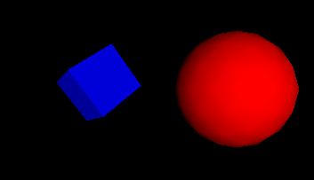
This file contains a simple scene defining a view of a red sphere and a blue box, lit by a directional light:
![]()
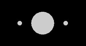
Reading the following file results in three spheres being drawn. The first sphere defines a unit sphere at the original named "Joe", the second sphere defines a smaller sphere translated along the +x axis, the third sphere is a reference to the second sphere and is translated along the -x axis. If any changes occur to the second sphere (e.g. radius changes), then the third sphere, (which is not really a reference to the second) will change too:
#VRML V2.0 utf8
Transform {
  children [
    DEF Joe Shape { geometry Sphere {} }
    Transform {
      translation 2 0 0
      children    DEF Joe Shape { geometry Sphere { radius .2 } }
    }
    Transform {
      translation -2 0 0
      children    USE Joe
    }

  ]
}
(Note that the spheres are unlit because no appearance was specified.)
![]()
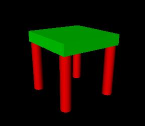
A simple chair with variable colors for the leg and seat might be prototyped as:
#VRML V2.0 utf8

PROTO TwoColorStool [ field SFColor legColor  .8 .4 .7
                      field SFColor seatColor .6 .6 .1 ]
{
  Transform {
    children [
      Transform {   # stool seat
       translation 0 0.6 0
        children
          Shape {
            appearance Appearance {
              material Material { diffuseColor IS seatColor }
            }
            geometry Box { size 1.2 0.2 1.2 }
          }
      }

      Transform {   # first stool leg
       translation -.5 0 -.5
        children
          DEF Leg Shape {
            appearance Appearance {
              material Material { diffuseColor IS legColor }
            }
            geometry Cylinder { height 1 radius .1 }
          }
      }
      Transform {   # another stool leg
       translation .5 0 -.5
        children USE Leg
      }
      Transform {   # another stool leg
       translation -.5 0 .5
        children USE Leg
      }
      Transform {   # another stool leg
       translation .5 0 .5
        children USE Leg
      }
    ] # End of root Transform's children
  } # End of root Transform
} # End of prototype

# The prototype is now defined. Although it contains a number of nodes,
# only the legColor and seatColor fields are public. Instead of using the
# default legColor and seatColor, this instance of the stool has red legs
# and a green seat:


TwoColorStool {
  legColor 1 0 0 seatColor 0 1 0
}
NavigationInfo { type "EXAMINE" }      # Use the Examine viewer
![]()
This Script node decides whether or not to open a bank vault given openVault and combinationEntered messages To do this it remembers whether or not the correct combination has been entered:
DEF OpenVault Script {# Declarations of what's in this Script node:eventIn SFTime openVaulteventIn SFBool combinationEnteredeventOut SFTime vaultUnlockedfield SFBool unlocked FALSE# Implementation of the logic:url "javascript:function combinationEntered(value) { unlocked = value; }function openVault(value) {if (unlocked) vaultUnlocked = value;}"}
Note that the openVault eventIn and the vaultUnlocked eventOut are or type SFTime. This is so they can be wired directly to a TouchSensor and TimeSensor, respectively. The TimeSensor can output into an interpolator which performs an opening door animation.
![]()
For example, the following IndexedFaceSet (contained in a Shape node) uses all four of the geometric property nodes to specify vertex coordinates, colors per vertex, normals per vertex, and texture coordinates per vertex (note that the material sets the overall transparency):
Shape {
  geometry IndexedFaceSet {
     coordIndex  [ 0, 1, 3, -1, 0, 2, 5, -1, ...]
     coord       Coordinate        { point [0.0 5.0 3.0, ...] }
     color       Color             { rgb [ 0.2 0.7 0.8, ...] }
     normal      Normal            { vector [0.0 1.0 0.0, ...] }
     texCoord    TextureCoordinate { point [0 1.0, ...] }
  }
  appearance Appearance { material Material { transparency 0.5 } }
}
![]()
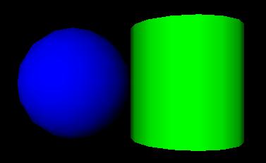
This example has 2 parts. First is an example of a simple VRML 1.0 scene. It contains a red cone, a blue sphere, and a green cylinder with a hierarchical transformation structure. Next is the same example using the Moving Worlds Transforms and leaves syntax.
#VRML V1.0 ascii
Separator {
    Transform {
        translation 0 2 0
    }
    Material {
        diffuseColor 1 0 0
    }
    Cone { }

    Separator {
        Transform {
            scaleFactor 2 2 2
        }
        Material {
            diffuseColor 0 0 1
        }
        Sphere { }

        Transform {
            translation 2 0 0
        }
        Material {
            diffuseColor 0 1 0
        }
        Cylinder { }
    }
}
#VRML V2.0 utf8
Transform {
    translation 0 2 0
    children [
        Shape {
            appearance Appearance {
                material Material {
                    diffuseColor 1 0 0
                }
            }
            geometry Cone { }
        },

        Transform {
            scale 2 2 2
            children [
                Shape {
                    appearance Appearance {
                        material Material {
                            diffuseColor 0 0 1
                        }
                    }
                    geometry Sphere { }
                },

                Transform {
                    translation 2 0 0
                    children [
                        Shape {
                            appearance Appearance {
                                material Material {
                                    diffuseColor 0 1 0
                                }
                            }
                            geometry Cylinder { }
                        }
                    ]
                }
            ]
        }
    ]
}
Note that the default Viewpoint will not have the objects centered in the view as shown above.
![]()
Here is an example that illustrates the order in which the elements of a Transform are applied:
Transform {
    translation T1
    rotation R1
    scale S
    scaleOrientation R2
    center T2
    ...
}
is equivalent to the nested sequence of:
Transform { translation T1
 children [ Transform { translation T2
  children [ Transform { rotation R1
   children [ Transform { rotation R2
    children [ Transform { scale S
     children [ Transform { rotation -R2
      children [ Transform { translation -T2
              ...
       }
      ]}
     ]}
    ]}
   ]}
  ]}
 ]
}
![]()
Moving Worlds has the capability to define new nodes. VRML 1.0 had the ability to add nodes using the fields field and isA keyword. The prototype feature can duplicate all the features of the 1.0 node definition capabilities, as well as the alternate representation feature proposed in the VRML 1.1 draft spec. Take the example of a RefractiveMaterial. This is just like a Material node but adds an indexOfRefraction field. This field can be ignored if the browser cannot render refraction. In VRML 1.0 this would be written like this:
...
RefractiveMaterial {
    fields [ SFColor ambientColor,  MFColor diffuseColor,
             SFColor specularColor, MFColor emissiveColor,
             SFFloat shininess,     MFFloat transparency,
             SFFloat indexOfRefraction, MFString isA ]

    isA "Material"
}
If the browser had been hardcoded to understand a RefractiveMaterial the indexOfRefraction would be used, otherwise it would be ignored and RefractiveMaterial would behave just like a Material node.
In VRML 2.0 this is written like this:
...
PROTO RefractiveMaterial [
            field SFFloat ambientIntensity  0 0 0
            field MFColor diffuseColor      0.5 0.5 0.5
            field SFColor specularColor     0 0 0
            field MFColor emissiveColor     0 0 0
            field SFFloat shininess         0
            field MFFloat transparency      0 0 0
            field SFFloat indexOfRefraction 0.1 ]
{
    Material {
            ambientIntensity  IS ambientIntensity
            diffuseColor      IS diffuseColor
            specularColor     IS specularColor
            emissiveColor     IS emissiveColor
            shininess         IS shininess
            transparency      IS transparency
    }
}
While this is more wordy, notice that the default values were given in the prototype. These are different than the defaults for the standard Material. So this allows you to change defaults on a standard node. The EXTERNPROTO capability allows the use of alternative implementations of a node:
...
EXTERNPROTO RefractiveMaterial [
            field SFFloat ambientIntensity
            field MFColor diffuseColor
            field SFColor specularColor
            field MFColor emissiveColor
            field SFFloat shininess
            field MFFloat transparency
            field SFFloat indexOfRefraction ]

    http://www.myCompany.com/vrmlNodes/RefractiveMaterial.wrl,
    http://somewhere.else/MyRefractiveMaterial.wrl
This will choose from one of three possible sources of RefractiveMaterial. If the browser has this node hardcoded, it will be used. Otherwise the first URL will be requested and a prototype of the node will used from there. If that fails, the second will be tried.
![]()
The target parameter can be used by the anchor node to send a request to load a URL into another frame:
Anchor {
  url "http://somehost/somefile.html"
  parameters [ "target=name_of_frame" ]
  ...
}
An Anchor may be used to bind the viewer to a particular viewpoint in a virtual world by specifying a URL ending with "#viewpointName", where "viewpointName" is the DEF name of a viewpoint defined in the world. For example:
Anchor {
  url "http://www.school.edu/vrml/someScene.wrl#OverView"
  children Shape { geometry Box {} }
}
specifies an anchor that puts the viewer in the "someScene" world bound to the viewpoint named "OverView" when the Box is chosen (note that "OverView" is the name of the viewpoint, not the value of the viewpoint's description field). If no world is specified, then the current scene is implied; for example:
Anchor {
  url "#Doorway"
  children Shape { Sphere {} }
}
binds you to the Viewpoint with the DEF name "Doorway" in the current scene.
![]()
A directional light source illuminates only the objects in its enclosing grouping node. The light illuminates everything within this coordinate system, including the objects that precede it in the scene graph--for example:
Transform {
  children [
    DEF UnlitShapeOne Shape { ... }
    DEF LitParent Transform {
      children [
        DEF LitShapeOne Shape { ... }
        DirectionalLight { .... } # lights the shapes under LitParent
        DEF LitShapeTwo Shape { ... }
      ]
    }
    DEF UnlitShapeTwo Shape { ... }
  ]
}
![]()
This simple example defines a PointSet composed of 3 points. The first point is red (1 0 0), the second point is green (0 1 0), and the third point is blue (0 0 1). The second PointSet instances the Coordinate node defined in the first PointSet, but defines different colors:
Shape {
  geometry PointSet {
    coord DEF mypts Coordinate { point [ 0 0 0, 2 2 2, 3 3 3 ] }
    color Color { color [ 1 0 0, 0 1 0, 0 0 1 ] }
  }
}
Shape {
  geometry PointSet {
    coord USE mypts
    color Color { color [ .5 .5 0, 0 .5 .5, 1 1 1 ] }
  }
}
This simple example defines a PointSet composed of 3 points. The first point is red (1 0 0), the second point is green (0 1 0), and the third point is blue (0 0 1). The second PointSet instances the Coordinate node defined in the first PointSet, but defines different colors:
![]()
The LOD node is typically used for switching between different versions of geometry at specified distances from the viewer. But if the range field is left at its default value the browser selects the most appropriate child from the list given. It can make this selection based on performance or perceived importance of the object. Children should be listed with most detailed version first just as for the normal case. This "performance LOD" feature can be combined with the normal LOD function to give the browser a selection of children from which to choose at each distance.
In this example, the browser is free to choose either a detailed or a less-detailed version of the object when the viewer is closer than 100 meters (as measured in the coordinate space of the LOD). The browser should display the less-detailed version of the object if the viewer is between 100 and 1,000 meters and should display nothing at all if the viewer is farther than 1,000 meters. Browsers should try to honor the hints given by authors, and authors should try to give browsers as much freedom as they can to choose levels of detail based on performance.
LOD {
  range [100, 1000]
  levels [
    LOD {
      levels [
        Transform { ... detailed version...  }
        DEF LoRes Transform { ... less detailed version... }
      ]
    }
    USE LoRes,
    Shape { } # Display nothing
  ]
}
For best results, specify ranges only where necessary, and nest LOD nodes with and without ranges.
![]()
This example interpolates from red to green to blue in a 10 second cycle:
DEF myColor ColorInterpolator {
  key        [   0.0,    0.5,    1.0 ]
  keyValue   [ 1 0 0,  0 1 0,  0 0 1 ] # red, green, blue
}

DEF myClock TimeSensor {
  cycleInterval 10.0      # 10 second animation
  loop          TRUE      # infinitely cycling animation
}

ROUTE myClock.fraction_changed TO myColor.set_fraction
![]()
The TimeSensor is very flexible. Here are some of the many ways in which it can be used:
1. Animate a box when the user clicks on it:
DEF XForm Transform { children [
  Shape { geometry Box {} }
  DEF Clicker TouchSensor {}
  DEF TimeSource TimeSensor { cycleInterval 2.0 } # Run once for 2 sec.
  # Animate one full turn about Y axis:
  DEF Animation OrientationInterpolator {
       key      [ 0,      .33,       .66,        1.0 ]
       keyValue [ 0 1 0 0, 0 1 0 2.1, 0 1 0 4.2, 0 1 0 0 ]
  }
]}
ROUTE Clicker.touchTime TO TimeSource.startTime
ROUTE TimeSource.fraction_changed TO Animation.set_fraction
ROUTE Animation.value_changed TO XForm.rotation
2. Play Westminster Chimes once an hour:
#VRML V2.0 utf8

Group { children [
  DEF Hour TimeSensor {
    loop          TRUE
    cycleInterval 3600.0         # 60*60 seconds == 1 hour
  }
  Sound {
    source DEF Sounder AudioClip {
      url "http://...../westminster.mid" }
    }
  }
]}
ROUTE Hour.cycleTime TO Sounder.startTime
3. Make a grunting noise when the user runs into a wall:
DEF Walls Collision { children [
  Transform {
    #... geometry of walls...
  }
  Sound {
    source DEF Grunt AudioClip {
      url "http://...../grunt.wav"
    }
  }
]}
ROUTE Walls.collision TO Grunt.startTime
![]()
Shuttles and pendulums are great building blocks for composing interesting animations. This shuttle translates its children back and forth along the X axis, from -1 to 1. The pendulum rotates its children about the Y axis, from 0 to 3.14159 radians and back again.
PROTO Shuttle [
    exposedField SFBool enabled TRUE
    field SFFloat rate 1
    eventIn SFBool moveRight
    eventOut SFBool isAtLeft
    field MFNode children ]
{
    DEF F Transform { children IS children }
    DEF T TimeSensor {
        cycleInterval IS rate
        enabled IS enabled
    }
    DEF S Script {
        eventIn  SFBool  enabled IS set_enabled
        field    SFFloat rate IS rate
        eventIn  SFBool  moveRight IS moveRight
        eventIn  SFBool  isActive
        eventOut SFBool  isAtLeft IS isAtLeft
        eventOut SFTime  start
        eventOut SFTime  stop
        field    SFNode  timeSensor USE T

        url "javascript:
            // constructor: send initial isAtLeft eventOut
            function initialize() {
                isAtLeft = true;
            }

            function moveRight(move, ts) {
                if (move) {
                    // want to start move right
                    start = ts;
                    stop = ts + rate / 2;
                }
                else {
                    // want to start move left
                    start = ts - rate / 2;
                    stop = ts + rate / 2;
                }
            }

            function isActive(active) {
                if (!active) isAtLeft = !moveRight;
            }

            function set_enabled(value, ts) {
                if (value) {
                    // continue from where we left off
                    start = ts - (timeSensor.time - start);
                    stop  = ts - (timeSensor.time - stop);
                }
            }"
    }

    DEF I PositionInterpolator {
        keys [ 0, 0.5, 1 ]
        values [ -1 0 0, 1 0 0, -1 0 0 ]
    }

    ROUTE T.fraction_changed TO I.set_fraction
    ROUTE T.isActive TO S.isActive
    ROUTE I.value_changed TO F.set_translation
    ROUTE S.start TO T.set_startTime
    ROUTE S.stop TO T.set_stopTime
}


PROTO Pendulum [
    exposedField SFBool enabled TRUE
    field SFFloat rate 1
    field SFFloat maxAngle
    eventIn SFBool moveCCW
    eventOut SFBool isAtCW
    field MFNode children ]
{
    DEF F Transform { children IS children }
    DEF T TimeSensor {
        cycleInterval IS rate
        enabled IS enabled
    }
    DEF S Script {
        eventIn  SFBool     enabled IS set_enabled
        field    SFFloat    rate IS rate
        field    SFFloat    maxAngle IS maxAngle
        eventIn  SFBool     moveCCW IS moveCCW
        eventIn  SFBool     isActive
        eventOut SFBool     isAtCW IS isAtCW
        eventOut SFTime     start
        eventOut SFTime     stop
        eventOut MFRotation rotation
        field    SFNode     timeSensor USE T

        url "javascript:
            function initialize() {
                // constructor:setup interpolator,
                // send initial isAtCW eventOut
                isAtCW = true;

                rot[0] = 0; rot[1] = 1; rot[2] = 0;
                rot[3] = 0;
                rotation[0] = rot;
                rotation[2] = rot;

                rot[3] = maxAngle;
                rotation[1] = rot;
            }

            function moveCCW(move, ts) {
                if (move) {
                    // want to start CCW half (0.0 - 0.5) of move
                    start = ts;
                    stop = start + rate / 2;
                }
                else {
                    // want to start CW half (0.5 - 1.0) of move
                    start = ts - rate / 2;
                    stop = ts + rate / 2;
                }
            }

            function isActive(active) {
                if (!active) isAtCW = !moveCCW;
            }

            function set_enabled(value, ts) {
                if (value) {
                    // continue from where we left off
                    start = ts - (timeSensor.time - start);
                    stop  = ts - (timeSensor.time - stop);
                }
            }"
    }
    DEF I OrientationInterpolator {
        keys [ 0, 0.5, 1 ]
    }
    ROUTE T.fraction_changed TO I.set_fraction
    ROUTE I.value_changed TO F.set_rotation
    ROUTE T.isActive TO S.isActive
    ROUTE S.start TO T.set_startTime
    ROUTE S.stop TO T.set_stopTime
    ROUTE S.rotation TO I.set_values
}
In use, the Shuttle can have its isAtRight output wired to its moveLeft input to give a continuous shuttle. The Pendulum can have its isAtCCW output wired to its moveCW input to give a continuous Pendulum effect.
![]()
Robots are very popular in in VRML discussion groups. Here's a simple implementation of one. This robot has very simple body parts: a cube for his head, a sphere for his body and cylinders for arms (he hovers so he has no feet!). He is something of a sentry - he walks forward, turns around, and walks back. He does this whenever you are near. This makes use of the Shuttle and Pendulum above.
DEF Walk Shuttle {
    enabled FALSE
    rate 10
    children [
        DEF Near ProximitySensor { size 10 10 10 }
        DEF Turn Pendulum {
            enabled FALSE

            children [
                # The Robot
                Shape {
                    geometry Box { } # head
                }
                Transform {
                    scale 1 5 1
                    translation 0 -5 0
                    children [ Shape { geometry Sphere { } } ] # body
                }
                DEF Arm Pendulum {
                    maxAngle 0.52 # 30 degrees
                    enabled FALSE

                    children [
                        Transform {
                            scale 1 7 1
                            translation 1 -5 0
                            rotation 1 0 0 4.45 # rotate so swing
                                                # centers on Y axis
                            center 0 3.5 0

                            children [
                                Shape { geometry Cylinder { } }
                            ]
                        }
                    ]
                }

                # duplicate arm on other side and flip so it swings
                # in opposition
                Transform {
                    rotation 0 1 0 3.14159
                    translation 10 0 0
                    children [ USE Arm ]
                }
            ]
        }
    ]
}

# hook up the sentry.  The arms will swing infinitely.  He walks
# along the shuttle path, then turns, then walks back, etc.
ROUTE Near.isActive TO Arm.enabled
ROUTE Near.isActive TO Walk.enabled
ROUTE Arm.isAtCW TO Arm.moveCCW
ROUTE Walk.isAtLeft TO Turn.moveCCW
ROUTE Turn.isAtCW TO Walk.moveRight
![]()
Here is a simple example of how to do simple animation triggered by a touchsensor. It uses an EXTERNPROTO to include a Rotor node from the net which will do the actual animation.
EXTERNPROTO Rotor [
    eventIn MFFloat Spin
    field MFNode children ]
 "http://somewhere/Rotor.wrl" # Where to look for implementation


PROTO Chopper [
    field SFFloat maxAltitude 30
       field SFFloat rotorSpeed 1 ]
{
    Group {
        children [
            DEF Touch TouchSensor { }, # Gotta get touch events
            Shape { ... body... },
            DEF Top Rotor { ... geometry ... },
            DEF Back Rotor { ... geometry ... }
        ]
    }

    DEF SCRIPT Script {
        eventIn SFBool startOrStopEngines
        field maxAltitude IS maxAltitude
        field rotorSpeed IS rotorSpeed
        field SFNode topRotor USE Top
        field SFNode backRotor USE Back
        field SFBool bEngineStarted FALSE

        url "chopper.vs"
    }

    ROUTE Touch.isActive -> SCRIPT.startOrStopEngines
}


DEF MyScene Group {
    DEF MikesChopper Chopper { maxAltitude 40 }
}


chopper.vs:
-------------
    function startOrStopEngines(value, ts) {
        // Don't do anything on mouse-down:
        if (value) return;

        // Otherwise, start or stop engines:
        if (!bEngineStarted) {
            StartEngine();
        }
        else {
            StopEngine();
        }
    }

    function SpinRotors(fInRotorSpeed, fSeconds) {
        rp[0] = 0;
        rp[1] = fInRotorSpeed;
        rp[2] = 0;
        rp[3] = fSeconds;
        TopRotor.Spin = rp;

        rp[0] = fInRotorSpeed;
        rp[1] = 0;
        rp[2] = 0;
        rp[3] = fSeconds;
        BackRotor.Spin = rp;
    }

    function StartEngine() {
        // Sound could be done either by controlling a PointSound node
        // (put into another SFNode field) OR by adding/removing a
        // PointSound from the Separator (in which case the Separator
        // would need to be passed in an SFNode field).

        SpinRotors(fRotorSpeed, 3);
        bEngineStarted = TRUE;
    }

    function StopEngine() {
        SpinRotors(0, 6);
        bEngineStarted = FALSE;
    }
}
![]()
Moving Worlds has great facilities to put the viewer's camera under control of a script. This is useful for things such as guided tours, merry-go-round rides, and transportation devices such as busses and elevators. These next 2 examples show a couple of ways to use this feature.
The first example is a simple guided tour through the world. Upon entry, a guide orb hovers in front of you. Click on this and your tour through the world begins. The orb follows you around on your tour. Perhaps a PointSound node can be embedded inside to point out the sights. A ProximitySensor ensures that the tour is started only if the user is close to the initial starting point. Note that this is done without scripts thanks to the touchTime output of the TouchSensor.
Group {
    children [
        <geometry for the world>,

        DEF GuideTransform Transform {
            children [
                DEF TourGuide Viewpoint { jump FALSE },
                DEF ProxSensor ProximitySensor { size 10 10 10 }
                DEF StartTour TouchSensor { },
                Shape { geometry Sphere { } }, # the guide orb
            ]
        }
    ]
}

DEF GuidePI PositionInterpolator {
    keys [ ... ]
    values [ ... ]
}

DEF GuideRI RotationInterpolator {
    keys [ ... ]
    values [ ... ]
}

DEF TS TimeSensor { cycleInterval 60 } # 60 second tour

ROUTE ProxSensor.isActive TO StartTour.enabled
ROUTE StartTour.touchTime TO TS.startTime
ROUTE TS.isActive TO TourGuide.bind
ROUTE TS.fraction TO GuidePI.set_fraction
ROUTE TS.fraction TO GuideRI.set_fraction
ROUTE GuidePI.outValue TO GuideTransform.set_translation
ROUTE GuideRI.outValue TO GuideTransform.set_rotation
![]()
Here's another example of animating the camera. This time it's an elevator to ease access to a multistory building. For this example I'll just show a 2 story building and I'll assume that the elevator is already at the ground floor. To go up you just step inside. A ProximitySensor fires and starts the elevator up automatically. I'll leave call buttons for outside the elevator, elevator doors and floor selector buttons as an exercise for the reader!
Group {
    children [

        DEF ETransform Transform {
            children [
                DEF EViewpoint Viewpoint { }
                DEF EProximity ProximitySensor { size 2 2 2 }
                <geometry for the elevator,
                 a unit cube about the origin with a doorway>
            ]
        }
    ]
}
DEF ElevatorPI PositionInterpolator {
    keys [ 0, 1 ]
    values [ 0 0 0, 0 4 0 ] # a floor is 4 meters high
}
DEF TS TimeSensor { cycleInterval 10 } # 10 second travel time

DEF S Script {
    field SFNode viewpoint USE EViewpoint
    eventIn SFBool active
    eventIn SFBool done
    eventOut SFTime start
    behavior "Elevator.java"
}

ROUTE EProximity.enterTime TO TS.startTime
ROUTE TS.isActive TO EViewpoint.bind
ROUTE TS.fraction_changed TO ElevatorPI.set_fraction
ROUTE ElevatorPI.value_changed TO ETransform.set_translation
![]()